lunes, 2 de marzo de 2015

Dynamical analysis of the sit to stand movement

In order to simplify the analysis, there are some considerations that should be taken before proceeding with the calculations,

1     Initial considerations:


 The human body has been divided in four groups:
o    The first group is formed by the feet, which are considered immobile and serve inertial reference system for the entire Sit-to-stand movement.
o    The second group corresponds to the legs, which rotate on reference of the feet with ankle’s axis.
o    The third group is made up of the thighs, which rotate on reference of the legs with knee’s axis and finally.
o    The fourth group, which, for reasons of simplifying calculations, consider together the trunk, head and upper limbs. This rotates on reference of the third element (thighs) with knee’s axis with hip’s axis.
 The relative parameters: weight, center of gravity, location and radius of gyration, which have been used for this work, are based on anthropomorphic models, obtained from samples of body parts, made by Dempster-Winter (1955, amended in 2009) and Zatsiorsky-Seluyanov, (1996, amended in 2002). See Table 02.

Segment
Center of gravity (%)
Relative Weight (%)
Radius of gyration
Kxx
Radius of gyration
Kyy
Radius of gyration
Kzz
Head and neck
60.4
0.0694
0.362
0.312
0.376
Trunk
49.5
0.4346
0.372
0.191
0.347
Arm
43.6
0.0271
0.285
0.158
0.269
Forearm
43
0.0162
0.276
0.121
0.265
Hand
50.6
0.0061
0.628
0.401
0.513
Thigh
43.3
0.1416
0.329
0.149
0.329
Leg
43.3
0.0433
0.251
0.102
0.246
Foot
42.9
0.0137
0.257
0.124
0.245
TABLE 02: Human body parameters

2     Method of Lagrange – EULER formulation

2.1     Lagrange -equation

$$L=\sum { { E }c_{ i }- } \sum { { E }p_{ i } } $$
$$\sum { { E }c_{ i } } =\frac { 1 }{ 2 } \sum _{ i }^{ n }{ \left[ \overline { v } _{ k }^{ T }{ m }_{ k }{ \overline { v }  }_{ k }+\overline { w } _{ k }^{ T }{ D }_{ k }{ \overline { w }  }_{ k } \right]  } $$
$$\sum { { E }p_{ i } } =-\sum _{ i }^{ n }{ \left[ { m }_{ k }\overline { g } ^{ T }{ \overline { C }  }_{ k } \right]  } $$

Where:

vk:
Translational speed of the k-th element
wk:
Rotational speed of the k-th element
mk:
Mass of the k-th element
Dk:
Inertia tensor of the k-th element regarding X0Y0Z0 and moved to its center of mass..
Ck:
Center of mass of the k-th element
g:
Gravity

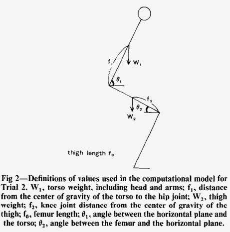
3     Method of Newton – EULER formulation

o    The θ1, θ2, θ3, angles were taken on reference of the horizontal axis.
o    Each element is taken as a rigid body.
o    Motion of various part of the body occur in a vector plane so that rotations of the body may be disregarded.
o    Various joint of the body may be expressed as a series of links
o    Each joint has a single axis
o    The center of gravity for each body segment is located along the line extending from one joint to the other.
o    The upper body, including the arms, may be expressed as a single, uniform volume.
o    W1, f1, W2, f2, f0 are defined as follows, according to the report by Matsui: W1, 56% of body weight; f1, 45% of sitting height; W2, 10% of body weight; f2, 58% of femur length; f0, actual measured distance from the outer knee joint to the greater trochanter of the femur.


Comparison between the results of calculation of torque by the Lagrange-Euler equation and the Newton-Euler formulation


4     Conclusions

  • Motion capture is an excellent tool for estimating the direct and inverse kinematics of our system; however, this procedure should be standardized, by parameterizing measures and environmental conditions where it is recorded. Once the recording data is made, it should be consider the ankle as a fixed point throughout the sitto-stand process, allowing this, a better data record.
  • The Lagrange equation and Denavit-Hartemberg representation let us parameterize the kinematic analysis (position, velocity and acceleration) and dynamic (Forces and Toques) versus time, achieving these, the calculus of maximum torques and forces on each element of our model, by noticing that we can consider that we need 1N-m for each kilogram of user’s mass to get manage the sit-to-stand movement. However, it is necessary to apply an additional safety factor when selecting the actuator motor to be used in our exoskeleton.
  • Newton-Euler formulation and Lagrange-Euler show similar results and graphics, corroborating thus the dynamic and kinematic analysis are correct.

Artículo expuesto en el 9th international Convention on Rehabilitation Engineering and Assistive Technology (i-CREATe 2015) del Enabling Technology Festival en Singapur - powered by IEEE


Análisis Cinemático del paso de la sedestación a la bipedestación


Se consideró un sistema multicuerpo de tres grados de libertad, todos ellos de rotación y ubicados en el tobillo, la rodilla y la cadera.


De los parámetros D-H, obtenemos las siguientes matrices

Cabe mencionar que para el estudio cinemática, y posteriormente dinámico, del paso de la postura sentada a la bipedestación, se hizo una toma de datos mediante la captura de movimiento de una persona sana. 

Ello con el fin de analizar las posiciones, velocidades y sobretodo, aceleraciones picos, que se producen en el sistema estudiado.


Obtenidas las posiciones de cada articulación, se calculan las velocidades y aceleraciones angulares y lineales tanto teóricas y experimentales.

Análisis Biomecánico del paso de la sedestación a la bipedestación

El estudio del paso de la postura sentada a la bipedestación se puede dividir en tres fases.

Fase I o de Inicio:
En esta fase el Centro de Gravedad (CG) se acelera en sentido horizontal hasta adquirir la máxima velocidad en esta dirección, por lo que algunos autores como Roebroekm la denominan también fase de aceleración.

Fig. 1. Fase de inicio

Fase II o de despegue o transición.
Esta fase comprende desde la máxima velocidad horizontal del CG hasta conseguir la máxima velocidad vertical.

Fig. 2. Fase de despegue

Fase III, de ascenso y estabilización
Esta fase comprende desde la máxima velocidad vertical del movimiento, produciéndose una elevación de todo el cuerpo que desplaza verticalmente el CG hasta estabilizarlo dentro de la nueva base de sustentación. Al darse en esta fase la velocidad vertical negativa, se denomina también fase de desaceleración.
Fig 3 Fase de Estabilización

miércoles, 8 de octubre de 2014

Summary of An Analysis of Sit to Stand movements


Introduction
•This paper has analyzed the movements involved in rising from a knee-high chair in 12 healthy men weighing within ±10% of standard body weight. A regular series of transition points was observed in the angles of the hip, knee, and ankle joints throughout the sit-to-stand movement, which was classified into six stages.

•The ability to stand from a sitting position., of course, makes other vital activities such as walking possible. Patients who are unable to stand not only are severely limited in terms of daily activities: they present a greater burden to those who must care for them.

Aims of this study

1. How do the angles oft he lower limbs change throughout the process of rising from a chair. and how are these angles affected by the speed of rising (Trial 1).
2. How much hip and knee extension torque is required per kilogram of body weight to complete the sit-to-stand movement (Trial 2).
3. During the sit-to-stand movement, how much load is being eserted on the muscles required for extension (Trial 3).


Trial 1: Measurement of Course-of-Time Changes in the Angles of the Hip, Knee, and Ankle Joints during Sit-to-Stand Movement•Subjects were asked to place their feet flat on the floor at shoulder’s width, and to stand with arms folded.
• The chair was adjusted to knee height for each subject and legs were positioned before standing so that dorsiflexion of the ankle joint was 15’ (fig I ). 
  
• Vectors were analyzed every 0.05 seconds so that changes in leg joint angles could be calculated while the subject was in motion.
• The categories were as follows:
  - (1) Fast sit-to-stand (0.8-I .4 seconds) (F-Stand)
  - (2) Slow sit-to-stand (3.0-4.0 seconds) (S-Stand)
  - (3) Natural sit- to-stand ( 1.7-1.3 seconds) (N-Stand).

Trial 2: Computation Models of the blinimum Unilateral Hip Joint and Knee Joint Extension Torque Required to Complete the Sit-to-Stand Movement
• At a given moment. the value for expressing torque for flexion ofthe hip joint is as follows (when force is applied by the weight of the torso):

H = w1f1*cos(theta1)/2 (fig 2). 

• Similarly, the torque for flexion of the knee joint using the weight of the torso and thigh is: 

K = w1(f0*cos(theta2) - f1*cos(theta1))/2 + w2f2*cos(theta2). 

• If only the following factors involving torque at the hip joint and knee joint are considered, the subject should be able to stand if torque is maintained in the direction of joint extension throughout the standing process
• It must be noted, however. that the success of this theoretical model depends on the assumptions presented in table 1


The maximum values of H and K (Hmax and Kmax) were obtained and then divided by each subject’s body weight to yield Hmax and Kmax per kilogram of body weight (Hmax/BWkg, Kmax/BWkg).
During N-Stand, the subject must be able to exert extension torque in excess of Hmax and Kmax at each joint throughout the sit-to-stand movement.
In this respect, therefore, Hmax and Kmax represent the minimum unilateral joint extension torque required for completing the sit-to-stand movement.


Results of Trial 1

• From a seated position in the chair (T1), the subject first flexes the torso forward slightly (T2). The hips are lifted off the chair (T3), then the hip joint reaches maximum flexion (T4). Maximum dorsiflexion is then exerted at the ankle joint (T5), after which the subject attains a standing position (T6) and stabilized balance (T7).

• Figure 4 shows the average percentage of time spent on each stage by the I2 healthy subjects


Calculate of H 
• Hip extension torque continued to increase after the buttocks left the chair (T3) and maximized when the forward inclination of the torso also reached maximum. Afterward, torque gradually decreased.

Calculate of K
• Knee extension torque was at its greatest when the buttocks left the chair (T3), then gradually decreased.


Discussion
•Standing is an act of voluntary muscle control, and movements may be altered by the individual at will; in this study, however, a definite pattern was seen when able-bodied people stood up without thinking.
• This system of classification enabled us to determine more accurately the stage at which patients experience difficulty.
• In general, the inability to stand may result from one or more of the following:
  - (I) loss of muscle strength
  - (2) paralysis or muscle coordination disorders:
  - (3) loss of balance;
  - (4) neurological or psychological disorders leading to a lack of interest in physical activity; and
  - (5) pain in the joints, limited range of motion,6 and other factors.
• Whatever the cause. a loss of muscle strength always follows. 

Conclusions
• Standard muscle strengthening exercises using weights or muscle exercisers may be inappropriate therapy in the rehabilitation of some patients with symptoms of muscular atrophy. In many such cases it may be better to focus on muscle training that involves repetition of basic movements. Standing, an activity of inestimable value to the patient. should definitely be incorporated in such therapy programs.

• As elderly and disabled populations continue to grow. we recognize the impact that a common activity such as rising from a seated position can have concerning the quality of life. A basic understanding of the sit-to-stand movement is therefore an essential component to rehabilitation studies.

sábado, 19 de abril de 2014

About Exoskeletons - State of Art ( Part Xero )

Well, this is an old post, but I think it's still interesting.


I found the best information at EPFL's web.
http://biorob.epfl.ch/cms/page-36366.html )
imitation

They work with an italian research institute
http://www-arts.sssup.it/tiki/tiki-index.php?page=robotics+for+neurorehabilitation ).


The method is the CPG ( Central Pattern Generators )

"Using CPG to control exoskeletons Exoskeletons are particular rehabilitation robots that are worn like an outer shell of the body. In collaboration with the ARTS lab at Scuola Superiore Sant'Anna (Pisa, Italy), we developed an innovative control method for an elbow exoskeleton (the NEUROExos) based on adaptive Central Pattern Generators. Conceptually, the elbow moving back and forth (continuous flexion/extension) can be viewed as an oscillator. The adaptive CPG comes to synchronize with this oscillator, and is able to learn its amplitude and frequency. In turn, the adaptive CPG feeds back some torque to the user through the joint actuator, therefore providing movement assistance..."

*********************************************************************************
I also asked for information to a good friend and he gave me two intereseted links
http://www.me.utexas.edu/~reneu/res/gait.html
alt text
They use the Statistical method for gait prediction and the Human gait pattern database was collected in Korean Institute of Science and Technology"

The other one lab is the Center of intelligent mechatronics
http://research.vuse.vanderbilt.edu/cim/research_orthosis.html

It's interesting but I couldn't download the publications.

*********************************************************************************
Furthermore, I found an webpage with and interesting state of art, but, it's from a year ago.
http://www.intorobotics.com/overview-of-exoskeleton-suits-assistant-paralyzed-and-military-exoskeletons/
University of Tokyo Exoskeleton

*********************************************************************************
Finally, I also found a French lab who analyses and models the human gait
(Institut de Science du mouvemént dans l'Université Aix Marseille)
http://www.ism.univmed.fr/spip.php?rubrique36&lang=fr
CNRSLogo tutelleLogo

Some links additional related


lunes, 14 de abril de 2014

Biomechatronics - State of Art (Part 1)


Some years ago, this word did not exist. So, some friends and me thought that it could be a good name for a group of projects in mechatronics applied to medicine, then, my friends and me call us "Biomechatronics group"; and we made some researches about the analysis gait, electromyography in lower and upper limbs and in lower limb exoskeleton's simulation and control design.
Today, maybe this word is not a trend yet, however, there are more and more people researching and developing this topics
In a quickly search on google, we can find lots of labs and research groups who are called "Biomechatronics group" or "Biomechatronic Lab", like us in the past, however, this is so great because we have now a lot of information and, I guess, there are more people who we can ask about it. Well, I hope most of them want to share their information.
Below, some of them

The Biomechatronics Group  ( MIT Media Lab )
" We are one of over 35 research groups within the MIT Media Lab. Our mission of this group is two fold. 
First, we seek to restore function to individuals who have impaired mobility due to trauma or disease through research and development. 
Second, We develop technologies that augment human performance beyond what nature intends."...

Photo


"Our mission is to develop wearable robots that improve human mobility. At present, the are studying ways to improve stability and energy efficiency for individuals whose strength and coordination have been affected by amputation, stroke, or aging using robotic prostheses and exoskeletons. We believe that appropriate mechanical assistance can not only restore function, but can enhance performance beyond typical human limits."...

Autonomous Systems and Biomechatronics Laboratory (ASB Lab) / University of Toronto"Our research focuses on developing intelligent mechatronics and robotic systems to assist humans in dangerous and stressful tasks and/or when a shortage of qualified personnel exists. In particular, our research is dedicated to the development of intelligent mechatronics systems with a primary focus on the design of robots and devices. Examples include the design of intelligent robotic systems, sensor agents and devices for search and rescue, exploration, surveillance, human-robot interaction, medical and health care applications."


"Our Biomechatronics Lab is dedicated ti improving quality of life by enhancing the functionality of artificial hands and their control via human - machine interfaces.
Our research is intended to advandce the design and control of human-machine systems as well as autonomous robotic systems."...

NEUROMECHANICS & BIOMECHATRONICS
"The goal of the NeuroMechanics & Biomechatronics section of biomechanical engineering is to improve the quality of life humans with a movement disorder. We develop new interventions and diagnostic techniques based on fundamental insight in (impaired) human motor control. This is accomplished through the combination of computational modelling of the neuromechanial system and experiments using techniques from system and control engineering, such as closed loop system identification. This basic research drives the development of devices to contribute to the improved diagnosis and treatment of participants with movement disorders."...
LOPES undressed

PROJECT PARTNERS

This European FP7 project involves partners from Iceland, the Netherlands, Germany, Belgium, and Italy.
RTEmagicC_ConsortiumLogos_png

BRL at MINES
"At Biomechatronics Research Laboratory, we focus on research problems at the intersection of robotics and human sensorimotor control system. We design and implement mechatronic and haptic interfaces that physically interact with humans for rehabilitation, augmentation and modeling of the human sensorimotor control system."...

Finally, I could find that in TUDelft - University of Technology, of Netherland,  exists an BioMechatronics & BioRobotics group (http://www.3me.tudelft.nl/en/about-the-faculty/departments/biomechanical-engineering/sections/biomechatronics-biorobotics/) and even, the speciality in Biomechatronics of the Master of Science BioMedical Engineering (http://www.tudelft.nl/en/study/master-of-science/master-programmes/biomedical-engineering/msc-programme/specialisations/biomechatronics/).
Furthermore, by chance, I could find also an very interesting opencourseware about Biomechatronics.
Let's try and enjoy.